The following is an inexpensive tank heater controller.
I started by purchasing a "ViaAqua, Aquarium heater, 250 watts, Titanium" from "amekaaquatic" on Ebay. This unit has an external temperature controller attached to a 250W Titanium heater. The picture on Ebay shows a perfect unit for this modification as the controller seems to have 1) power input plug, 2) temperature sensor on cord, and 3) power output to the heater. The units actually ship with a little mod. A controller has the power input, and a thicker wire that goes to the heater and then splits from there to the sensor. This made the mod a little more complicated (just a little).
Also as part of this project you need a controllable power box at the desired capacity. I wanted a single 1800W box (15A circuit). This would be built as a 1800W receptacle, relay controlled with a plug input. For time reasons, I had this built by JehmCo (www.jehmco.com) for $70 including shipping. The delivered unit was very professional looking and to code -- always happy with JehmCo.
So, next step was to CUT the cord going to the heater. I did this after it exited from the controller so I maintained the water resistant seals to the controller. I also cut the smaller sensor wire coming out of the heater (the left most wire in the picture of the heater). Interesting that the wires coming out of the controller are:
blue: fused neutral
brown: switched live
green: sensor
yellow: sensor
The two sensor wires leaving the HEATER are new wires that are blue and brown (smaller gauge than the power). Confusing!
I sealed the cut on the sensor wire at the heater using Starbrite Liquid Electrical Tape, AND a piece of Storehouse UL listed Marine Heat Shrink Tubing.
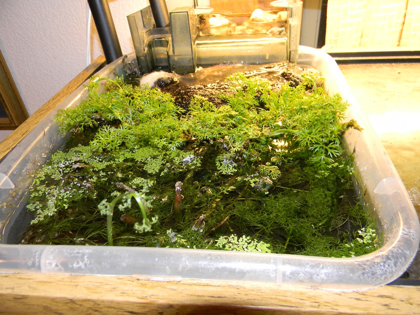
The wire to the heater was "fixed" with a length of outdoor extension cord (16/2) with the male end attached. The female or socket end of the extension cord was used to "fix" the power output of the controller. You can see this setup in the first picture. The controlled box (from JehmCo) has two plugs -- one for mains power in (that goes out the bottom of the picture) -- and one for the control input. The control input is shown plugged into the orange socket wire from the controller.
The final connection was to extend the sensor wire -- I used household lamp wire -- at the cut wire coming out of the controller.
Total cost: $107 (including cost of sacrificed extension cord).

MW -- PS: do not undertake this project unless you are confident in you ability to do electrical work to code and in a safe and knowledgeable manner. Always respect mains power. This is for info only and not for the inexperienced. I do not take responsibility for any actions you do based on this info.